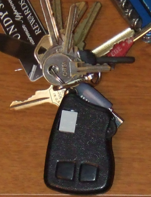
Naked and in a key fob.
Index of mRNG:
Naked and in a key fob.
Are you confused by choices? Who isn't? There are just so many things to decide. White, rye, or wheat? Pinstripes or polka dots? Feast or fast? Well, don't worry because help is on the way!
I'm introducing the world's first, portable, hand held, decision maker powered by truly random numbers. Sure, my competition has long sold decision makers for 1, 5, 10, or 25 cents. But can they decide between more than two choices? NO! Are they really random? NO! NO! My decision maker can choose between up to 16 options, and the results are truly unpredictable, according to the postulates of quantum (or at least statistical) mechanics.
Now, I hear some of you object, "But Leon, I can make decisions on my own." Perhaps, but they're often arbitrary, illogical, and regrettable. Why agonize over both the choice and the results, when you can just worry about the latter? Try something new! Stop worrying! Tell determinism to take a hike! Destroy the paradox of choice! Give randomness a try!
Compared to most modern inconveniences, my mRNG is simple to operate. The device has only two buttons and one thumb wheel. Orient the mRNG display side up, and with the metal ring pointed away from you (like in the picture at the top of the page and in the video below). The left button turns the device on. Hold it down to power the device. A new number is then displayed about 30 times a second -- too fast for you to read. Holding the second button down stops the screen from updating so that you can read the newest random number.
The thumb wheel sets the upper bound of the random number range -- 0 to that bound inclusive. The upper bound can be set as high as 15. Since the display has only one digit, the numbers are in hexadecimal (10-15 are displayed as a-f). Changing the range will cause the new upper bound to be displayed for ~.75 seconds before more random numbers are generated. When the device is powered on it will also display the current upper bound for that amount of time. It's possible to turn the thumb wheel to be right on the border between two numbers (e.g., between 8 and 9), in which case the mRNG may keep changing the upper bound between those values. Simply turn the thumb wheel a little to move it away from the border.
Note that '6' and 'b' (11 in hexadecimal) look similar on the display. The difference is that the top segment of the display is lit for '6' but not for 'b'. (See the exciting Wikipedia article on Seven-segment display character representations! I used the left column of characters.)
Demonstration of mRNG operation. First, the range is adjusted. Then several numbers are generated. Then the process is repeated.
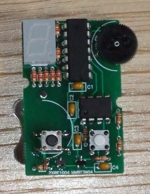
Fitting everything into a key fob meant everything had to be small. That turned out not to be a challenge in and of itself, but it meant using a coin battery, which in turn meant trying to draw 4mA or less (the current version uses 6-7mA, which is close enough). This was achieved mainly by turning off and on different parts of the circuit as needed. When it's generating a random number, the display is off. The elements of the display itself are pulsed on and off quickly giving the illusion of being on continuously (and meaning that no more than 4 segments are ever one at one time). With that in mind, let me explain the design a bit further. (The source code and complete schematic are available below.)
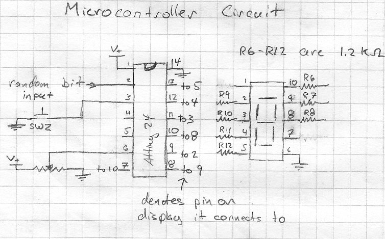
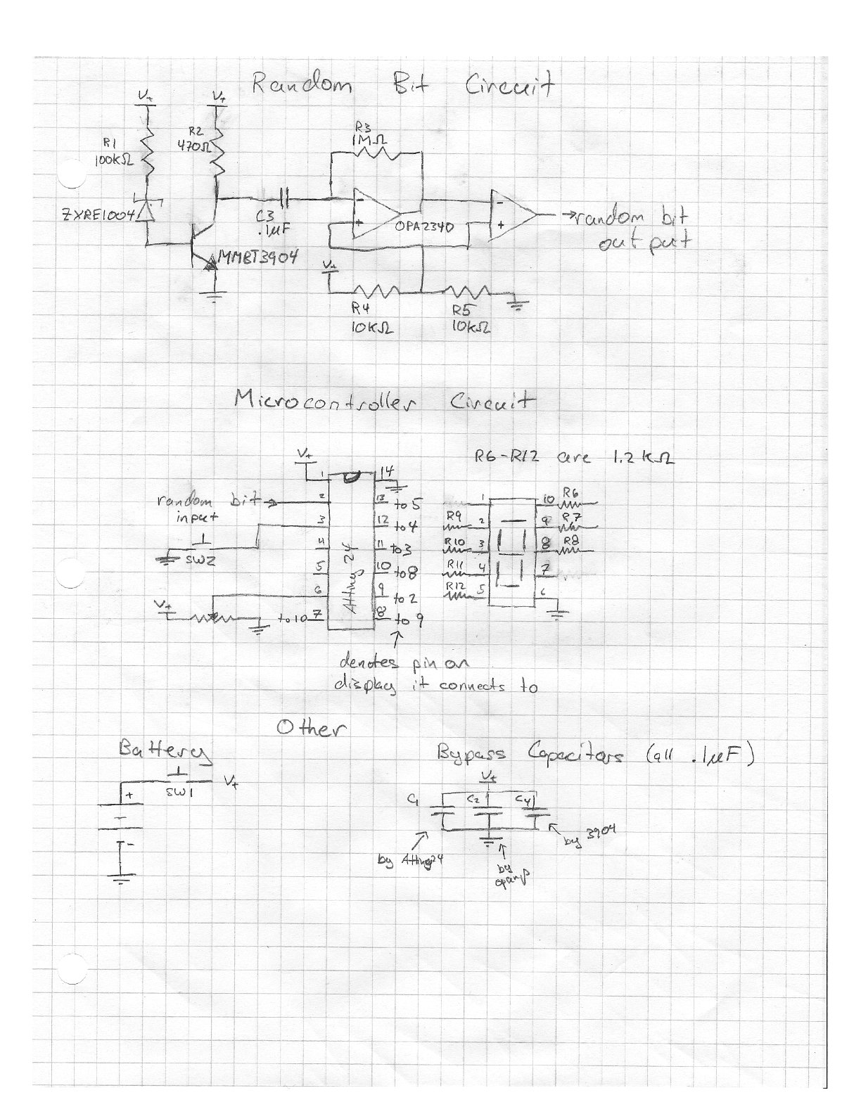
The schematic for the microcontroller part.
Instead of using a PIC microcontroller (like I did in my last project, or sequential logic, like in previous versions), I decided to use an AVR. Both had the right hardware features, but the PIC lacked a free C compiler for Linux and OS X. Writing assembly code was interesting, but I had better uses for my time. I chose the ATtiny24 because it had the right number of pins and an analog to digital converter.
The microcontroller drives the LEDs through 1.2kΩ resistors (that value was chosen as a good balance between high brightness and low current -- other values will work). The switch doesn't need an external pull-up resistor because the microcontroller has internal ones. No attempt is made at debouncing the switch because it isn't necessary. The potentiometer is attached to the microcontroller's analog to digital converter and is used to set the upper bound of the random number range.
The random bit input is connected through one of the digital input pins. Again, no attempt is made to "debounce" it -- the average frequency of the random digital output was much slower than the clock speed of the microprocessor (1 MHz), so timing issues should be negligible. However this was measured for the random bit generating circuit alone, without the noise from the microcontroller. The random digital input is debiased in software using the Von Neuman method and a linear feedback shift register acting as a randomness extractor.
The microcontroller runs at 1MHz using its 8MHz internal oscillator. Future versions may use the internal 128kHz internal oscillator to save some power, but I expect the savings to be minimal.
The source code is available below.
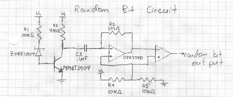
The schematic for the random, bit generating part.
This circuit was inspired by Terry Ritter's random noise sources. Diodes are often used for noise sources, but noisy low voltage diodes are hard to come by. For that reason, we use a 1.22V bandgap voltage reference (the ZXRE1004FFTA) that emulates a zener diode.
Its datasheet shows that it requires at most 8μA of current to function (4μA typical) to function, and that it is noisiest at this current (page 3). So we want to run it at close to that current, both to save power and get as much noise from it as possible. Given that the MMBT3904 transistor (datasheet) has a base to emitter voltage drop of ~.75V, the voltage reference has a drop of 1.22V, and the battery provides ~3V, that means the drop across the resistor is about 1V. So a 100kΩ resistor (R1) will let about 10μA of current through (probably a little less, since the battery's voltage will drop).
Given this current through the base of the transistor and the transistor having a gain of a couple 100, we expect ~2mA to flow through the collector of the transistor. We want the output from the collector to be roughly at 1.5V (in the middle of our voltage range), and a 750Ω will do that. However, any relatively close resistor value will be fine, so I'm using a 470Ω resistor (R2) which yields a drop of ~1 volt.
This signal is passed through a capacitor -- so that we can have different voltage levels -- and then amplified by op-amp. Because we want a digital signal, we want an "infinite" gain from the amplifier. However, we also need the average voltage level at the two inputs to be the same, so we use really big resistor (1MΩ -- R3). Even the high slew rate of the OPA2340's output isn't enough to make this signal digital -- the output didn't hit the maximum or minimum voltage in testing. So this amplified signal is fed in the the second op-amp on the chip, and that amplifies it to digital goodness (the output is only the maximum or minimum voltage). That's ready to feed in to the microcontroller. The output looked to have a fairly even distribution of ones and zeros, but it is debiased in the microcontroller just to be safe.
| Image (not to scale, borrowed from Digikey) | Quantity | Part Name and Digikey Link | Name on PCB | Description and Notes |
|---|---|---|---|---|

OR  |
1 | MCP6282-E/P-ND
OR OPA2340PA |
OPAMP | Low voltage operation, low current draw, and a high slew rate are requirements for this op-amp. The second one has these, but is expensive. The first doesn't have as high a slew rate, so it doesn't amplify the noise as well, but it seems to do an acceptable job since we use both op-amps. |
 |
1 | ATTINY24V-10PU | attiny24 | The ATtiny24 has the right number of IO pins for the job. This is the low voltage version. |
 |
1 | MMBT3904 | MMBT3904 | A surface mount version of the venerable 2N3904 NPN transistor. Other transistors would probably work, but the value of R2 might need to change. |
 |
1 | ZXRE1004FFTA | ZXRE1004 | The voltage reference (fake zener diode) that provides the random noise for this device. |
 |
1 | LTS-4802BJR-H1 | 7seg | A 7 segment LED display which puts out a fair amount of light for the current it draws. |
 |
1 | EVL-HFAA01B24 | P | A 20K linear thumb wheel potentiometer. |
 |
1 | FSM2JSMA | SW1 | A surface mount tact switch (the dimensions are important -- many switches will not fit). |
 |
1 | EVQ-PAE04M | SW2 | A through hole tact switch (the dimensions are important -- many switches will not fit). |
 |
1 | 3003 | The holder for the 20mm coin battery. We don't need a separate bottom holder -- the pad is part of the PCB. | |
 |
4 | 399-4151-ND | C1-C4 | .1μF ceramic capacitor. |
 |
1 | CFR-12JB-100K | R1 | 100kΩ 1/6W resistor. |
 |
1 | CFR-12JB-470R | R2 | 470Ω 1/6W resistor. |
 |
1 | CFR-12JB-1M0 | R3 | 1MΩ 1/6W resistor. |
 |
2 | CFR-12JB-10K | R4,R5 | 10kΩ 1/6W resistor. |
 |
7 | CFR-12JB-1K2 | R6-R12 | 1.2kΩ 1/6W resistor. |
 |
1 | CA-4, 2 BLACK | The case. Some other colors are available. Note that the case doesn't come with the cutouts for the display or thumb wheel; there are instructions below for how to make them. | |
 |
1 | P189-ND | 3V 20mm coin battery | |
 |
1 | The PCB | In order to get good contact between the battery and the square pad on the PCB, I usually melt a little solder on the square pad so that it's a little higher than the surrounding PCB. |
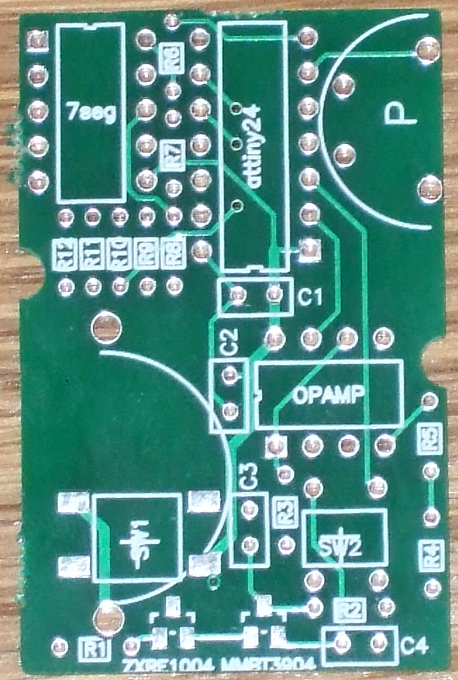
Unless there's interest, I'm not going to go in to the gory here since it's more or less self documented (e.g. you see that R4 is a 100k ohm resistor, so you put it at the location marked R4 and solder it in), but I do have some general advice. If you're looking for more basic information on soldering, check out any of the many good tutorials online.
For the surface mount parts, I find what works well is to build up a little solder on one of the pads, hold the part to it with tweezers, heat the pin so that the solder on the pad wets to it, and adjust the parts orientation to your liking with the heat applied. Then you can go about soldering the other pads without trouble. As far as surface mount parts go, these ones are pretty tame.
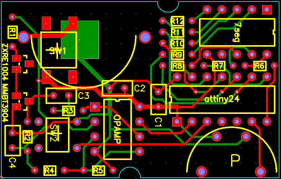
Red traces are on the top of the board, and green traces are on the back. (Click for larger image)
I think the best order to solder things in, is from smallest to largest. Start with the ZRE1004 and MMBT3904, then the capacitors, then the resistors, and finally the larger things. The only real clearance issue is with C3. Make sure to trim its leads short before attaching the battery holder, or else they will make contact. On a related note, be sure to solder C3 and C4 before the battery holder -- you can't really do it the other way around. The only things you can really solder in the wrong orientation are the display, the microcontroller, and the op-amp. Since there are no sockets, you've only got one shot. Pin one goes in the hole with the square pad (near the end where the silkscreen has a notch). Check twice and solder once. Also, the through hole switch needs to be as far in as it will go; otherwise it'll be depressed by the case's button pad without the button pad being pressed. To get it all the way in, it sometimes helps to straighten out the switch's leads before putting it in the PCB.
When you're done soldering, you need to make two holes in the case, one for the thumb wheel and one for the display. These instructions won't make much sense until you have the case in your hands, and see how everything fits. I recommend using a sharp pocket knife and a punch-and-die type nibbler to make the holes (although you could probably do ok with only a sharp knife). First, cut the hole for the thumb wheel -- you only have to cut the top part of the case. You can see where to cut by lining up the PCB's notches with the PCB support posts/screw holes. Then, bore a hole in the case where the display goes (you can use the knife), and stick the nibbler in cut out an appropriate sized hole (cut a little, check fit, repeat until it fits). There are two posts on the inside of the top of the case for the buttons' support to connect to. The top one has to be removed -- it is just about where a corner of the display goes. The button's support can be trimmed back to the connector for the other post. Finally, the PCB support posts on the top half of the case may need a little shaving to get everything to fit together snug, and there may be a nub on the inside of the case (left over from its manufacture) that needs to be removed. Update: I now usually use a CNC mill to make the openings in the case. If you have access to one, I recommend you use it.
Well, I've got some PCBs. They were under $4 a pop. Let me know if you want one.
If there's interest, I'll whip up a kit. If I make 25 kits, it'd work out to about $15 of parts a piece (there's not much of a bulk discount for fewer than 25). So maybe $20 including shipping and a little for me. Again, let me know if you're interested.
If you can't make one, I'll consider building you one if the price is right. I am a starving grad student after all... (Although I'm also a very busy one, so I may well say no.)
Most of the electronic dice/"random" number generators you're likely to find schematics for are not random in the slightest. They simply count over their range very quickly in a very regular way. For example, if such a circuit wanted to generate a random number between 1 and 6, it would simply count 1, 2, 3, 4, 5, 6, 1, 2, 3, 4, 5, 6, 1, 2, 3, 4, 5, 6, and so on. When you ask it for a number, it simply gives you the number it was at when you interrupted it. The unpredictability in its output comes solely from the unpredictability in when exactly you press its buttons. Granted, these numbers look random enough for many purposes, but the fact is that these devices are entirely deterministic.
Well, it's no LED Christmas tree kit; I'll warrant you that. I'd say this is more of an intermediate project. There are a couple of surface mount components, but they're not too bad. Mostly, there are just a bunch of parts in a small space, so you want to get everything right the first time. If your a newbie, you might succeed. You might not. At any rate, it's less risky than my first soldering project with surface mount parts (it did not succeed).
It was too hard to fit entrails in the the keyfob...
In truth, pseudorandom number generators are closely related to randomness extractors. Those are algorithms that can take imperfect (biased or correlated) random numbers and clean them up. One of the extractors I use in the code is similar to a linear feedback shift register, which can be used as a pseudorandom number generator. If you want, you can kind of think of what I'm doing as continuously seeding this with random numbers. I think it's easier just to think of it as an extractor. See this PAQ for more information.
Done (see 0:36)
Sure, you could make a deterministic version of this. You'd just remove the random number generating circuity and have the numbers generated in the program somehow. For example, it could just count from 0 to max very fast (how most electronic "random" number generators work), and when you press the button, it stops counting. Or you could program a pseudo-random number generator like with a shift register. "Better" pseudo-random number generators exist, but they'd be overkill. But then again, so are real random numbers...
I evaluated it on its own. It was clear that the voltage reference and transistor were generating more noise than anything else, and the circuit was amplifying it correctly. The voltage reference and transistor are semiconductor devices, so I assume that the noise they produce is random. Things change a little when the microcontroller circuit is added. Now, the noise generated by the rest of the circuit is comparable to the noise generated by the voltage reference and transistor. This makes it harder to evaluate, because much of that noise is deterministic (e.g. the display is turned on and off every so many milliseconds, the microcontroller runs at 1Mhz, etc.) However, the display is turned off when random numbers are being generated, so it is my hope that the voltage reference and transistor are then the major source of noise, and thus the noise is random. However, I do not have the equipment needed to confirm this. My 30 year old oscilloscope only does so much...
Initially I just used the Von Neumann method, which works well against bias (e.g. if random numbers coming from the hardware are 0 60% of the time and 1 40% of the time) but not correlation (e.g. if a 1 is more likely to be followed by another 1). However, the resulting numbers clearly had issues (e.g. when generating numbers 0-9, 7 would appear with twice the frequency of the others). Now, in addition to that, I feed the random bits in to the software equivalent of a linear feedback shift register (the bits are XORed in along with the feedback). I want to better analyze this method, but some simulations and results show this does a good job against both bias and correlation (although I've mostly looked at bias so far). You can think of the shift register as an extractor, hash function, or pseudorandom number generator. They're all related.
I haven't had time to do much analysis yet, but here's a start. I recorded 258 numbers (by hand -- otherwise I'd have done more) on a device running code revision 16. So we'd expect each to show up 25.8 times on average. Here are the results:
| Number | Number of times output |
| 0 | 23 |
| 1 | 22 |
| 2 | 22 |
| 3 | 32 |
| 4 | 26 |
| 5 | 25 |
| 6 | 31 |
| 7 | 24 |
| 8 | 31 |
| 9 | 22 |
We hypothesize that these numbers should be uniformly distributed, so chi-squared comes out to 5.72 using Pearson's chi-square test. Since we have 9 degrees of freedom, that gives us P=0.7676. In a nutshell, that means that given a uniform distribution, results this far away from uniform (or farther) would occur ~76% of the time. So, we cannot reject the hypothesis that the distribution was uniform. In short, these numbers look pretty good from a chi-square test perspective.
Of course, there are many other test to try since different tests look at different things. For example, this test didn't check if there was any correlation between numbers (e.g. if 2 is more likely to follow 1 then that wouldn't be picked up by this test).
Yes.
I designed the board with Pad2Pad's cost-free software, which is super easy to use, and I've been happy with the PCBs they made, so I have no reason to change. EagleCAD is not so easy to use, and I haven't had the time to figure it out. You want a file in that format? Make it, send it my way, and I'll post it.
If you want to contact me, the best way is by email.


Leon's Mini Random Number Generator by Leon Maurer is licensed under a Creative Commons Attribution-ShareAlike 3.0 Unported License.
